Leave Your Message

CONTACT

Leave Your Message

Why Is a Blowout Well a Critical Oilfield Safety Tool?

A Blowout Well is often discussed as a critical oilfield safety tool, but the wording needs careful attention. In professional well-control practice, the blowout preventer, or BOP, is the primary equipment designed to control unexpected formation pressure. It seals the wellbore, supports pressure management, and helps crews respond before hydrocarbons reach the surface.

That distinction matters. A “Blowout Well” is not normally a standalone device. It usually describes a well exposed to blowout risk or a well-control situation. Reliable safety planning depends on accurate terminology, verified equipment ratings, and disciplined procedures. During drilling, pressure changes can appear through rising pit volume, unexpected flow, or altered pump pressure. These signs require immediate evaluation by trained personnel.

The danger is real.

A failed response can release oil, gas, and high-pressure fluids within seconds. A properly maintained BOP stack provides a physical barrier while crews stabilize the well. Its performance depends on inspection records, pressure testing, hydraulic control systems, and competent decision-making. Field experience also shows that equipment alone cannot prevent every incident. Human error, poor communication, or misunderstood readings may weaken several safety barriers at once.

This article examines why Blowout Well control remains central to oilfield safety. It considers pressure containment, emergency response, maintenance, and workforce training. It also recognizes an uncomfortable reality: safety systems can look reliable until conditions change. Continuous verification is essential. Professional guidance, manufacturer requirements, and applicable regulatory standards should always shape final operating decisions.

Why Is a Blowout Well a Critical Oilfield Safety Tool?

What a Blowout Well Is and Why It Matters in Oilfield Operations

A blowout well is a well with uncontrolled flow from the reservoir to the surface or another underground zone. Oil, gas, or formation fluids can escape when pressure exceeds the well’s barriers. The term is sometimes used loosely. Strictly speaking, a blowout well is a hazardous condition, not a safety tool. The safety tools are the blowout preventer, pressure-control equipment, monitoring systems, and trained response teams.

In serious incidents, crews may drill a relief well to reach the damaged well underground. They then pump heavy fluid or other approved materials to overcome formation pressure and restore control. This process requires accurate surveys, pressure data, geological knowledge, and careful coordination. A small error in depth or pressure assumptions can worsen the situation. That risk is easy to underestimate.

Daily prevention remains more important than emergency action. Crews check barrier integrity, test shut-in procedures, monitor pit levels, and investigate unexpected pressure changes. A rising tank level may look minor during a busy shift. It may signal influx. Clear communication matters too. One missed warning can affect everyone near the well. Even experienced personnel can become overconfident when operations appear stable. I would question any procedure that depends on memory alone. Written steps, independent verification, and practical drills make response faster and more reliable. Safety depends on disciplined decisions before control is lost.

How Blowout Wells Help Control Unplanned Pressure and Fluid Flow

A blowout well can release formation fluids faster than surface equipment can safely contain them.

In practice, pressure control depends on several barriers, including the blowout preventer, drilling fluid, casing, and cement. When these barriers fail, a relief well may become the safest response. It is drilled toward the uncontrolled well and carefully intersected near its lower section. Engineers then pump heavy kill fluid or cement through the relief well. This changes the pressure balance underground and restricts further oil, gas, or water movement.

Pressure is not always visible at the surface. That makes early interpretation essential. A small rise in pit volume, unexpected flow, or reduced drilling-fluid density can signal a developing kick. API well-control guidance emphasizes verified barriers, pressure testing, and trained response teams. The IOGP Well Control Incident Reporting System also shows why consistent event reporting matters: weak signals often appear before major loss-of-control events. Details matter.

The Deepwater Horizon investigation recorded 11 worker deaths and an estimated 4.9 million barrels released from the Macondo well, according to the National Commission’s 2011 report. That event exposed how quickly pressure, gas expansion, and delayed decisions can combine.

A relief well is not an instant solution. It requires accurate ranging, directional drilling, pressure monitoring, and disciplined coordination. Sometimes the plan still needs revision. That uncomfortable possibility should be built into every well-control exercise.

Key Safety Equipment Used in Blowout Well Management

Why Is a Blowout Well a Critical Oilfield Safety Tool?

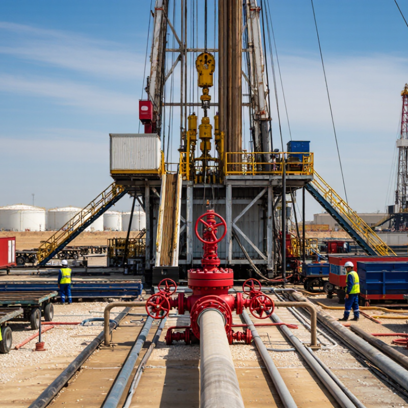
A blowout well requires layered well-control equipment, not one heroic device. The blowout preventer stack sits above the wellhead. Annular preventers seal around irregular pipe, while ram preventers close specific pipe sizes. Shear rams may cut tubulars and seal the well, but their performance depends on design, pressure, and pipe position.

The accumulator stores hydraulic power for rapid closure. A remote control panel lets crews activate the stack away from the rig floor. Choke manifolds control pressure through adjustable flow paths. Mud-gas separators remove expanding gas before contaminated fluids reach open tanks. Diverter systems protect shallow formations during early drilling, when underground blowout risks remain serious.

Pressure sensors and real-time alarms provide another layer, although alarms can be missed during noise, darkness, or confusion.

API Standard 53 and API Recommended Practice 59 describe expectations for BOP systems and well-control operations. The IOGP Safety Performance Indicators Report 2022 recorded 20 fatalities across member-company operations, showing why equipment reliability and human decisions must work together.

Industry incident reviews repeatedly identify weak kick detection, poor communication, and delayed shutdowns. During a simulated kick, a crew may notice rising flow, unstable pit volume, or unexpected pressure first. That moment is unforgiving. A red light can still be misunderstood.

Maintenance records, pressure tests, certification checks, and realistic drills matter as much as hardware. No checklist is perfect. Supervisors should question assumptions, especially when readings conflict.

Step-by-Step Response Procedures During a Well Control Emergency

Why Is a Blowout Well a Critical Oilfield Safety Tool?

A blowout preventer protects the well when formation pressure exceeds control limits. It is not a magic shield. It depends on tested barriers, trained crews, and fast decisions. The NIOSH report Fatalities in the Oil and Gas Extraction Industry, 2003–2009, recorded a fatality rate of 27.5 per 100,000 workers. That was nearly seven times the rate for all U.S. workers. These figures make well control discipline more than a procedural requirement.

During an emergency, the driller should identify abnormal flow, pit gain, or pressure changes immediately. Stop the operation and follow the approved shut-in procedure. Close the appropriate preventer. Confirm flow has stopped. Record casing and drill-pipe pressures. Notify the company representative and emergency coordinator. Keep nonessential personnel away from the well center.

The team must then verify both primary and secondary barriers. Pressure readings should be monitored continuously. Do not circulate kill fluid until the well-control supervisor confirms the plan. If pressure rises unexpectedly, pause and reassess. Activate alarms, evacuation routes, and muster controls when conditions worsen. The IOGP Safety Performance Indicators report for 2023 recorded 31 fatalities among participating companies, showing that serious exposure remains real. In practice, crews sometimes delay shut-in decisions because readings seem uncertain. That hesitation needs review. A quiet panel can still hide a dangerous influx.

Why Is a Blowout Preventer a Critical Oilfield Safety Tool?

During a well-control emergency, the blowout preventer helps close the well, contain formation pressure, and provide time to circulate an influx out of the well with appropriately weighted drilling fluid. The chart presents a standard response sequence; site-specific well-control procedures and competency requirements always take precedence.

Operational Limits, Risks, and Maintenance Requirements

Why Is a Blowout Well a Critical Oilfield Safety Tool?

A blowout preventer is a critical barrier against uncontrolled formation pressure. It closes around, or cuts through, tubulars during a well-control emergency. Its protection depends on correct pressure ratings, fluid compatibility, and verified installation. The equipment must match the well’s maximum anticipated surface pressure. Temperature, corrosive fluids, and gas composition also affect performance. A small mismatch can become a serious failure.

Operational limits matter every day. Operators must not exceed rated working pressure, closing pressure, temperature, or allowed wear limits. High-pressure testing can reveal leaks, but it cannot prove every future condition. Trapped pressure remains dangerous after closure. Personnel should confirm pressure readings before opening any component. Poor communication, damaged hoses, and delayed decisions can weaken the barrier. H2S zones require suitable detection, respiratory protection, and emergency procedures. Keep people clear.

Maintenance is more than changing seals. Technicians should inspect rams, annular elements, hydraulic lines, valves, flanges, and control systems. Function tests and pressure tests should follow approved procedures and regulatory requirements. Test results need clear records, including pressure, duration, fluid, and observed leakage. Stored equipment also needs protection from moisture, corrosion, and temperature extremes. Spare seals must be compatible and within shelf life. Field experience shows that neglected small defects often become operational failures. Checklists help, but they are not perfect. A rushed test can create false confidence. Regular drills should examine both equipment response and human judgment.

Why Is a Blowout Well a Critical Oilfield Safety Tool? — Operational Limits, Risks, and Maintenance Requirements
Safety System or Component Primary Safety Function Typical Operational Limits or Control Criteria Main Failure or Exposure Risk Inspection, Testing, and Maintenance Requirements
Blowout Preventer (BOP) Stack Provides a pressure-control barrier that can close around drillpipe, casing, or open hole to prevent uncontrolled formation-fluid flow. The stack working-pressure rating must meet or exceed the approved well design pressure and anticipated surface pressure. Common land and offshore ratings include 3,000, 5,000, 10,000, and 15,000 psi, but the selected rating is well-specific. A pressure rating mismatch, incorrect assembly, damaged sealing elements, or poor installation can result in loss of well control. Verify certification, pressure rating, configuration, and barrier diagrams before installation. Inspect after rig moves, major well-control events, reassembly, or component changes. Test according to the approved well program and applicable regulations.
Annular Preventer Seals around different tubular sizes and, within its approved capability, can close on an irregular or non-circular object. The annular element has a lower pressure capability than many ram preventers and may require reduced pressure when closing on certain pipe sizes or when stripping pipe. The manufacturer’s operating envelope and the well program control allowable pressure. Excessive pressure, repeated closure cycles, high temperature, elastomer deterioration, or closing on an unsuitable object can damage the sealing element. Inspect the packing element for cuts, extrusion, hardening, heat damage, and abnormal wear. Confirm hydraulic closing pressure and accumulator performance. Replace the element when inspection findings or service limits require it.
Pipe Rams Seal around a specified outside diameter of drillpipe, casing, or tubing to isolate the wellbore. Pipe rams are size-specific and should not be closed on an incompatible tubular size. Their working-pressure rating must match the BOP stack design and expected well pressure. Using the wrong ram size, closing on tool joints, excessive wear, or damaged rubber seals may prevent a pressure-tight closure. Confirm ram size and identification before use. Inspect sealing rubbers, ram blocks, hydraulic cylinders, hinges, and locking mechanisms. Perform function and pressure tests after installation and at the intervals specified by the well-control program.
Blind and Shear Rams Blind rams seal an open hole; shear rams are designed to cut specified tubulars and may provide emergency wellbore isolation when other barriers are unavailable. Shearing capability depends on tubular grade, wall thickness, tool joints, internal pressure, and the specific ram design. The shear function must never be assumed capable of cutting every downhole component. Failure to shear, incomplete sealing, trapped pressure, or accidental shearing of critical equipment can create severe well-control and recovery hazards. Confirm the approved shear schedule and equipment compatibility. Function-test hydraulic systems and verify control-panel indications. Inspect cutting components, seals, hydraulic chambers, and locking systems during scheduled maintenance.
Choke Manifold Controls and safely routes formation fluids during well-kill operations, controlled circulation, and pressure management. Every pressure-containing component must have a working-pressure rating equal to or greater than the maximum expected pressure for the flow path. Choke size, erosion allowance, and temperature limits must be considered. Erosion, plugging, incorrect valve alignment, vibration, and high-velocity multiphase flow can cause loss of containment or an inability to control pressure. Inspect valves, flanges, chokes, flow lines, supports, gauges, and bleed-off arrangements. Check for erosion and leakage after high-rate or abrasive-flow events. Confirm correct valve line-up before circulation.
Kill Line and Choke Line Provide controlled flow paths for pumping kill fluid into the well and directing returns through the choke manifold. The line rating must exceed the maximum planned operating pressure. Flow rates should remain within design limits to control erosion, friction pressure, and equipment loading. Blocked lines, plugged valves, failed connections, erosion, or an incorrect flow path can prevent well killing or redirect high-pressure fluids toward personnel. Pressure-test the lines and valves according to the approved test schedule. Inspect supports, clamps, flexible hoses, unions, flange bolts, erosion-prone bends, and valve positions. Remove or isolate defective components before operations continue.
Accumulator and Hydraulic Control Unit Stores hydraulic energy needed to operate BOP functions when rapid closure is required. Precharge, hydraulic-fluid volume, operating pressure, and reserve capacity must meet the equipment design and regulatory requirements. Low temperature, leaks, and insufficient reserve can reduce closing performance. Loss of hydraulic pressure, depleted accumulators, damaged hoses, control-valve failure, or inadequate backup power may prevent BOP operation. Check pressure, precharge, fluid level, leaks, alarms, gauges, hoses, control valves, and backup sources. Function-test all required BOP movements and verify that the available reserve can complete the planned sequence.
Choke and Kill Control Panel Allows personnel to operate and monitor well-control valves, chokes, and pressure readings from a controlled location. Controls, gauges, and remote functions must remain available, clearly identified, and within their calibrated measurement range. Operating procedures must specify acceptable response times and communication methods. Incorrect labeling, instrument drift, failed remote controls, poor visibility, or communication breakdown can result in an incorrect response during a kick. Calibrate pressure gauges and transmitters at the required interval. Function-test remote valves, alarms, emergency shutdowns, displays, and communication systems. Keep valve line-up diagrams current and visible.
Mud-Gas Separation and Gas Handling Separates entrained gas from drilling fluid and directs gas to a safe discharge or handling system during well-control operations. The separator must be operated within its pressure, flow-rate, liquid-level, and gas-handling design limits. Vent locations and ignition-control requirements must be maintained. Overpressure, liquid carryover, gas release, blocked vents, or inadequate separation can expose personnel to fire, explosion, asphyxiation, or toxic gases. Inspect vessel integrity, relief devices, piping, level controls, vents, drains, ignition-control measures, and gas-detection interfaces. Verify that emergency response procedures address gas release and evacuation.
Well-Control Monitoring and Kick Detection Identifies abnormal changes in flow, pit volume, return flow, pump pressure, or drilling parameters before a small influx develops into a blowout. Alarm thresholds must be established for the specific well and rig system. No single pit-volume or flow-change value is universally suitable because it depends on hole size, pumping rate, surface system, and operating conditions. Delayed detection, sensor failure, poor calibration, equipment noise, or failure to investigate a small anomaly can allow an influx to grow rapidly. Calibrate and function-test flow meters, pit-level sensors, totalizers, alarms, and data displays. Conduct regular crew drills for flow checks, shut-in procedures, and escalation of abnormal trends.
Pressure Testing and Function Testing Confirms mechanical integrity and operational readiness before the equipment is relied upon as a well-control barrier. Test pressures, hold times, test sequences, and acceptance criteria must follow the approved well program, equipment rating, and applicable legal requirements. Test pressure must not exceed the weakest rated component. Improper test isolation, trapped pressure, incorrect test pressure, undocumented results, or testing against an unsuitable component can create equipment damage or false confidence. Perform tests before critical operations, after installation or reassembly, after significant maintenance, and after events that may affect integrity. Record pressure charts or digital results, leaks, anomalies, corrective actions, and authorization to return to service.
Personnel Competence and Emergency Response Ensures that the crew can recognize a kick, shut in the well, activate barriers, communicate clearly, and execute the approved well-kill plan. Personnel must be trained and authorized for their assigned duties. Drills should reflect the actual rig configuration, communication system, alarms, escape routes, and expected well hazards. Unclear authority, delayed decisions, inadequate training, fatigue, poor handover, or failure to follow the shut-in checklist can turn a manageable influx into a blowout. Conduct documented drills, competency assessments, toolbox meetings, and pre-tour equipment checks. Review lessons learned after drills and incidents, and update procedures when the well design or equipment configuration changes.
Important note: The pressure values and operating criteria shown are representative industry ranges or control principles, not universal operating instructions. Actual limits must be taken from the approved well program, equipment certificates, manufacturer documentation, regulatory requirements, and the weakest component in the pressure-containing system.